Search This Blog

Wednesday, April 12, 2017

Energy Meter connection;Single Phase; Three Phase; CT operated Energy meters

In every domestic, industrial and commercial establishment there is need of electricity and for measuring power consumption energy meters are installed in all establishments.

For domestic connections usually direct meters are used means power supply wires are directly connected at input and output is withdrawn from its output and for large and commercial establishments CT operated energy meters are used as direct meters are not feasible to install as size of these energy meters will be very high. It is usually recommended to install CT operated meters if load requirements from energy meters are more than 15 KW.
CT operated meter is most preferable meters in all establishments as they are easy to install and operation is very simple.
In this article we study about installation of energy meters both Houses and as well as commercial and industrial establishments:-

In Domestic connections both single phase and three phase energy meters are used:-

For single phase meters wiring is quite simple there are 4 terminals at the meter, 2 No’s for input power supply and 2 no’s for output power supply. Wiring diagram for installation of single phase energy meter is as below:-


Single Phase energy meter connections


For Three phase Energy meters:-
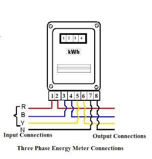
For installation of these meters there are 12 No.s terminals 6 no.s for three phase power supply at Input and 6 no’s for output power supply .
Connection for three phase energy meters are as below:-


Three Phase energy meter connections

CT operated energy meter installation:-
For installation of CT operated energy meters 1st you have to install CT’s at Input cable as per your load requirements. These energy meters can be used for measurement of consumption for any load only CT’s are required to be selected according to load. As power consumption indicated in energy meter is multiplied by CT ratio of energy meter.
Various Connection diagram for energy meter
(i)                 3 CT, 4 wire connections
(ii)               3 Wire, 2 CT connections
are as below:-

CT Operated Three phase energy meter connections


In these meters there are no output terminals as these energy meters are serving the purpose of measuring the energy consumed in circuit. CT output wires are connected at terminals provided for connections of CT’s and apart from CT connections there are three terminals provided for connections for three phase voltages.
Now after doing all connections CT ratio needed to be entered into energy meter so that energy meter reads the correct power consumption consumed in system. If you don’t enter correct CT ratio then you may not get correct results.
Now after doing all connections and programming in energy meter , energy meter starts working when power supply get charged.
There are energy meters also available where you need not enter CT ratio in energy meters instead energy consumption displayed on energy meter needed to multiplied by CT ratio to arrive at actual consumption.


There are many parameters which can be monitored through these energy meters. There are energy meters available in market which works on 2 Quadrant and 4 quadrant. 4 quadrant meters works on both lead and lag power factors i.e. energy meter reading keeps on increasing in case of lead power factor also. But on the other hand in 2 quadrant energy meters , energy meter works on lag power factor only i.e. these energy meters don’t work in lead power factor.

Friday, April 7, 2017

Single Phase preventer working and installation Procedure

Phase preventer are used in industries are having following advantages:-

1.       They uses to protect the motors and electrical systems in case of one/ two phase failure in three phase power system i.e. they can protect the system from single phasing.
2.       They protect the system in case phase sequence gets changed and phase sequence protects the system so that motors could not start operating in reverse direction.
3.       They also protect the system when voltage level falls below a particular level.
Phase preventer is also named as single phase preventer.
Installation of Phase preventer in electrical systems:-
Phase preventer consists of following:-
1.       Terminals for Three phase supply
2.       Terminals for auxiliary supply
3.       NO/ NC contact for interlocking
Connections for the relay as below:-

Single phase preventer connections

There are few additional settings provided on Phase preventer are:-
(i)                  Under voltage setting :- Do the Under Voltage setting to minimum
(ii)                Under voltage delay settings: Keep the Under Voltage Delay to minimum
(iii)               Unbalanced Voltage Settings:- Keep percentage Unbalanced to maximum

Now connect the three phase power supply at three terminal for three phase power supply
Now provide single auxiliary power supply at auxiliary power supply points.
Now finally connect Interlocking connections at Phase preventer so that when there is phase failure motor or required machine get tripped

Now turn ON power supply and Phase preventer get energized and if RED light on phase preventer get green then phase sequence is correct and voltage in all phases is above minimum under voltage setting.

If after energizing the Phase preventer LED light on Phase preventer glows RED then this means phase sequence needed to be changed of three phases Input supply or main supply. After changing phase sequence light made to glow green.


Also when Green light is on display of phase preventer then NO and NC will remains the same .  When phase sequence get changed then NO becomes NC and NC becomes NO so interlocking motor or machine get tripped.

Under Voltage Trip point setting:-
To protect equipment from under voltage it is always recommended to keep under voltage setting to as minimum as possible. If you don’t know the settings then adjust the under-voltage setting knob until LED starts glowing red. Now Slowly adjust the knob to setting in such a way that relay starts glowing green. Now at that setting it will ensured that voltages are under acceptable limits.

Under Voltage Delay Settings:-
The delay set in this setting is the maximum time for which under voltage can exist in system before causing tripping of motor or machine.
Settings can be done in such a way that if setting is done too low then it may cause nascence tripping in the system. If setting is done too high then it may cause damage to motor or machine and purpose of installation get defeated.

Voltage Unbalance setting:-
Voltage unbalance is another setting provided on the relay. In any system maximum allowable unbalanced voltage is not specified. But it generally acceptable to level of (+-) 5% depending upon allowable limits specified on motor or machine terminal plate.

In every system there will not be perfectly balanced voltage in system. So Unbalanced voltage setting to be done accordingly, too low settings will cause unwanted interruptions and too high settings will may cause damage to motor or machine.

Another way of doing the setting is to first adjust the knob for unbalanced voltage setting until relay starts glowing red , after that now slowly adjust the knob in such a way that LED starts glowing green.

As per NEMA %age Unbalanced Voltage= (Maximum Deviation from Average voltage/ Average Voltage)X 100

Where average voltage= (L1+L2+L3)/100

After doing all settings relay LED was glowing green.


Tuesday, April 4, 2017

Energy Savings with IE1, IE2 & IE3 Motors

Motors are part of every industry and commercial establishments and so it becomes very important to reduce the cost related to electricity to be reduced to as much as possible so as to increase profitability.
There are some important facts which you should must know about motors as per research done by International copper association India :-
(i)                  In industries motors usually accounts for 70% of power consumption
(ii)                In motors entire life major chunk i.e. 88% of total life cost is energy cost.
So it becomes very important to save electricity as much as possible as soon you reduce electricity bill you will save environment also.
So premium efficient motors are equally become very important as these motors has very low losses as these motor have used following for reducing losses:-
(i)                  Reduced stator copper losses as they have more active material
(ii)                Reduced iron losses by using high grade silicon steel
(iii)               Reduced friction and windage losses by using better fan design
There are following advantages of using Extra premium efficient motors over IE2 & IE3 motors:-
(i)                  Constant efficiency of motors from 60% of load to 100% of load
(ii)                Lower electricity consumption as losses are minimum , so power bill reduced
(iii)               These motors have greater ability to operate at higher temperature range.
(iv)              These motors have better thermal and electrical stresses
Indian Energy efficient Motors standard:-
Bureau of Indian standards introduced the standard for energy efficient motors in 1989 as IS:12615. This standard covers 4 pole with rating upto 37 KW.
Revision: I of IS:12615
Same was revised in 2004 to cover more motors this time standard covers :-
(i)                  2 Pole – 4 Pole Motors having rating from 0.37 KW to 160 KW
(ii)                6 Pole motors having rating from 0.37 KW to 132 KW
(iii)               8 Pole motors having rating from 0.37 KW to 110 KW
This revision also includes efficiency levels i.e. Eff1 & Eff2 and Test methodology for the same as per IEC 60034-2


Revision: II of IS:12615
In year 2011 same was again revised as Upon introduction of IEC 60034-30 for efficiency classification of induction motors and same was adopted by other countries. So in order to be in par with standard, standard was revisited and revised with following :-
(i)                  Motor range has been extended Now it will covers 2 Pole, 4 pole, 6 pole motors ranging from 0.37 KW- 375 KW.
(ii)                Motor testing standard should be IS:15999:2011 or IEC 60034-2-1
(iii)               New efficiency levels introduced: IE1, IE2 & IE3 (IEC 60034-30:2008)
(iv)              New parameters like Breakaway Torque, Current & full load current are included
How to find when to replace the motor?
There are following steps which you can follow in your industry to arrive at conclusion that whether we needed to replace motors or not:-
(i)                  Prepare database of all motors along with breakdowns in past.
(ii)                Prepare database for efficiency of motors as per motor name plate
(iii)               Takeout database of number of rewinding’s done in past.
(iv)              Checkout OEM data provided with motors about efficiency curves of motor and effects of every rewinding on motor efficiency. As per typical analysis for motors it has been found that for every rewinding there is drop in efficiency of motor form 1% to 5% for every rewinding.
From database we can also found that if motors are older than 8 to 10 years then definitely motors will be inefficient motors also over the period of time there might be rewinding of motors will be done which worse the inefficient motors.
It has been found that often repair/rewinding cost of medium and small motors (<50 KW) is often on higher side so it is often recommended to replace the same after certain period of time after complete analysis. 
After preparing all database checkout various efficient motors available in market and compare with your database. Now prepare a payback calculation sheet and you can definitely come out at some conclusion for replacement of motors.
Below cost benefit analysis of a typical 20 KW motor is done to strengthen viewpoint of replacement of medium and small size motors:-
Here loading of 80% is considered over whole year.
Running Hrs are taken as 20 Hrs per day and for whole year it will comes to be = 365 X 20 = 7300 Hrs
Annual Cost of energy for IE1 Motors= ((20* 0.8) X 7300 X 8)/ (0.887) = 1053438 Rs / Year
Annual cost of energy for IE2 Motors= (20*0.8) X 7300 X 8/ (0.906)= 1031346 Rs / year
Annual Cost of energy for IE3 Motors= (20*0.8) X 7300 X 8/ (0.921)= 1014549 Rs / year

Parameter
Standard Motor Eff2 (IE1)
Energy efficient Motor
(IE2)
High Efficient Motor (IE3)
Motor KW rating
20
20
20
Efficiency
88.7%
90.60%
92.10%
% Loading
80%
80%
80%
Running Hrs /Year
7300
7300
7300
Energy Cost/ KWH
8.0
8.0
8.0
So Annual Savings comes out to be

22092
38888
Purchase price of New Motor in Rs.
45000
55000
63000
Payback period

 5.4 month
5.6 Months

So from above we can see that there are huge savings in respect to energy bill with shifting from IE1 Motors to IE2 and IE3 motors.

Also there are saving even if we shift from IE2 Motors to IE3 Motors.

Monday, April 3, 2017

How to make extension board?

Extension board as the name implies it is used for extending the circuit means providing the power supply at the desired place.
Extension boards are part of every house ,every commercial establishment and even every industrial establishment. Extension boards are readily available in the market and these can be designed as per requirements.
There is very simple circuit diagram of an extension board. You can design extension board from one switch socket to as many as you required. It is easy to design the extension board at home very easily and it is very cheap method of constructing the extension board instead of buying the same as it is very costly affair.


Extension board consists of following:-
1. Switches
2. Sockets
3. Extension cord
4. Box on which switch sockets mounted

Below is the method for making an extension board. Circuit diagram for the same is as shown below:-
Extension board circuit diagram
Phase is circulated in sockets through switches and neutral and earth are connected at every socket directly.
You can install 5A or 15 A switch and sockets as per your load requirements.
If you are using 3 no.s 5A switch sockets then a 2.5 mmsq copper wire for phase, neutral and earth will be sufficient
If you are using 3 no.s ,15 A switch sockets then wire should be 4 mmsq copper.
As you keep on increasing no. of switch sockets you should have to increase the size of wire accordingly.
All connections should be tightly done and no loose wiring should be remain as otherwise it leads to short circuit and shocks. So double check should be done for checking tightness.

After doing the connections as stated above. Connect a plug top as per rating of switch and sockets and now you will ready to use your extension board.

Repairing Extension Board:-
You can also repair extension board very easily. If there is fault in any switch, Socket or wire then same can be replaced and repairing of extension board can be done.

One thing which must be kept in mind that if your are putting load on all sockets then connection for the same should be taken from socket or mcb of rating according to load connected to the extension board as otherwise it may leads to fault in socket or MCB from load is taken.

Cost of Making extension Board at Home:-
Cost of Making extension board is very low in comparison to extension board available in market .e.g.  an extension board consisting of anchor Make switch sockets will cost you around about 500-600 for 3 Switch/ sockets and if you made it at home you will save 50% cost i.e. cost of making extension board at home is 300-400/-
Also you will make good quality extension board at home.


Sunday, April 2, 2017

Inverter Air conditioner Working principle; Saving with Inverter AC

We have seen and used Air conditioners which directly run on electricity and consume power according to capacity of air conditioner irrespective of temperature settings of Air conditioners. Inverter technology in air conditioners has changed whole scenario in world of air conditioners. 


There are following advantages of inverter air conditioners:-
(i)                  Quieter operation
(ii)                More economical operation and lower down electricity bill


In Inverter technology , inverter equipped in air conditioners has the ability to control the compressor’s speed and so as the temperature which leads to draw lower current when temperature is set higher and near auto stop, which ultimately leads to lower power consumption.
Inverter used in this technology is like inverter used in houses for emergency power supply but added to this is microcontroller which used to automatically adjust the temperature and current of compressor.

Since it provides smooth operation as compressor start and stop are smooth as current is controlled to compressor through Voltage/ Frequency control method so jerk operations of compressors are avoided. Since there are no jerk operations so operation of these air conditioners is smooth and quieter. Smooth operation will leads to sharp fluctuations in load which extends life of both equipment and power source supply. This will leads to lower breakdowns.

Difference between Fixed Speed Compressors and Variable Speed Compressors:-

Fixed Speed compressors start and stop automatically at a particular set temperature but in Variable speed compressors inverter regulates the desired temperature by regulating the capacity of compressor.  
Fixed Speed compressors always runs at 100% capacity but in Variable speed compressors compressor runs at partial loads as per requirements.
Also in our houses we can’t ascertain the exact size required for a room which leads to oversized/ undersized air conditioners. So by using inverter AC’s oversize factor can be reduced. If we install higher capacity AC in our room then there will be higher power consumption  irrespective of working hours of air conditioner. But in inverter AC’s Power consumption will get controlled.
There are following advantages and disadvantages of using inverter Air conditioners:-

Advantages of Inverter Air conditioners:-
(i)                 Higher efficiency of air conditioners as no. of start and Stop cycles get eliminated
(ii)               Effective temperature control can be achieved
(iii)                Higher equipment life as these have smoother operation
(iv)                Lower breakdowns
(v)                 Quieter operation

Disadvantages of Inverter Air conditioners:-

There are following disadvantages of Inverter Air conditioners:-
(i)                   Energy loss during power conversion to DC and AC again leads to losses of 4-6 %
(ii)                 Higher initial cost as inverter leads to added cost
(iii)                Complexity of circuit made difficult to repair

Price and Payback period:-
A 1.5 Ton Air conditioner consumes 1.5 KWH as it is assumed that 1TR consumes 1KW etc
Calculation for 8hrs/ day

Operation of Fixed speed Air conditioners
For 8 hrs of operation power consumption will be = 1.5 X 8 = 12 units

For a Inverter AC
An Inverter AC will operate for 30 minutes and for rest 30 minutes it will maintain the temperature.  During maintaining the temperature for rest 30 minutes power consumption will be 300 W/Hr.
So power consumption /Hr= 0.750+0.300= 1.05 KWH
For 8 Hrs operation power consumption  will be= 1.05 X 8= 8.4 Units
So Power saving will be = 12- 8.4 = 3.6 KW/ 8 Hrs
So do your calculations before buying any Air conditioner.
There will be price difference of 10,000-15,000 between inverter Air conditioner and split Air conditioners.
So if we consider 12 Hrs operation for 180 days power saving with Inverter AC will be= 12.6 X 180 = 2268 Units/annually
Rate per unit = 8 Rs
So Annual Savings will be= 18144/-

So payback for inverter AC’s is 3 months so do consider these before buying the Air conditioners. 

To know about new technology in Air conditioners visit:-
http://electrialstandards.blogspot.in/2017/04/hybrid-conditioners-unknown-facts.html

Saturday, April 1, 2017

Hybrid Conditioners Unknown facts

In this world technology is keeps on changing so as the people. As people keeps on looking for new technology. Now you have seen that in air conditioners alone there are so many technology changes taking place. In past inverter Air conditioners were launched which consumes very low power. Now Hybrid Air conditioners are launched.

Now 1st under understand what is hybrid means???
Hybrid Air conditioner means which can run two power sources/fuel for running an air conditioner. In hybrid 1st source is electricity and another is by using solar energy.

These Air conditioners made to run on Solar power. These Air conditioners can run 100% on solar power. Another power source is taken as optional as in some cases when solar power is not available then that source can be used.


As these Air conditioners can run 100% on solar power these AC’s are equipped with inverter and battery system so that these air conditioners can run in night hours also. During day time these batteries get charged and will provide power through inverter in night hours. In Day time AC’s can run directly from solar power through inverter.

Companies which are making these AC’s are giving 25 years warranty on power generation capability of solar panels and 10 years warranty on solar panels. So this means that there isn’t any cost involve on solar panels replacement for life time, but following points must be taken care before buying these AC’s:-


1.       Space required for AC’s :- Since these AC’s are equipped with Inverter and batteries so Larger space will be required for accommodating the same.

2.       Life of Batteries and Inverter:- Since Manufacturers are giving warranty on solar panel for 10 years but warranty for inverter and battery will be maximum 2 years so do consider the cost of replacement of batteries and inverter while calculating maintenance cost.

3.       Sun facing House:- Do some technical before installation as if your house isn’t sun facing then your purpose of installation of these AC’s get defeated.  

4.       High Initial cost:- These AC’s will have very high initial cost almost double of other AC’s, as there is added cost of inverter, batteries, Solar panels.

Although these AC’s will reduce burden on your electricity by huge amount but above parameters must be taken care before doing comparison between AC’s.


These AC’s are very efficient and having copper condenser which required lower power.


Let’s check Viability of installation of these Air conditioners:-

Let’s take 1.5 ton 5 start AC having power consumption of 1200 Watt/Hr which will run for 12 hours whole year. Now let’s take a Hybrid AC. Now let’s compare them:-

Initial cost of 1.5 ton 5 star AC = 55000/-

Initial cost of 1.5 ton Hybrid AC= 130000  /-

Electricity consumption per day= 12 X 1200= 14.4 KW/Hour

Electricity consumption for whole year= 14.4 X 365 = 5256 units

Electricity Bill for whole year= 5256 X 8 = 42048 Rs

Now considering Maintenance cost for both AC’s as same then :-

Total Cost of 1.5 ton 5 Star AC = 55000 +42048 = 97048/-

Which means 2 years required for recovery of cost of Hybrid AC’s in case of whole year usage.
Now after 2 years you have to bear cost of replacement of Batteries which is approx.= 20000/-
So that cost will leads to 2.5 years of recovery.


In places where usage is only for 6 months then Rate of recovery will be 5 years . So do consider these factors while installation of these AC’s 

Friday, March 3, 2017

Unknown facts about cylindrical capacitors

Cylindrical capacitors:-
Unlike plate capacitors where 2 plates are used to form a capacitor, cylindrical capacitors are made by using two concentric cylindrical shells or wires and these two cylinders and wires are separated by using a dielectric medium.


Only difference between plate capacitor and cylindrical capacitor is its shape.

Electrical cable is best example for cylindrical capacitors.
How to calculate capacitance of a Cylindrical capacitor:-

For Calculating capacitance of a cylindrical capacitor let’s take radius of inner cylinder as r1 and outer cylinder as r2. Now let’s take permittivity of dielectric material used to form capacitor as  εa.

As in case of plate capacitor where one plate is acts cathode and other acts as an anode now in similar case let’s take inner cylinder charge per meter length on outer surface of inner cylinder as +q and similarly on inner surface of outer cylinder as –q coulombs.


In practical +q charge is considered to be on axis and outer circle is earthed so that person touching the capacitor doesn’t get the shock.

Cylindrical capacitors

Now for calculating capacitance of capacitor:-
Surface area of the coaxial cylinder = 2
x= Radius of cylinder a meter and
Length =1 meter

Now electrical field intensity at “x” meter away from center of inner cylinder is as below:-


Ex =     Q                   Volt/Meter
        2πεoεax       

Where εo= Permittivity of vacuum or permittivity of free space, its value is 8.84 x 10-12 Farad/meter


Potential difference between two plates or two cylinders is as below:-

Charge calculations cylindrical capacitors


So more will be the length of capacitor more will be the capacitance.

Capacitor is also known as condenser.